Software Lab 05: The Great Divide
Files
This lab description is available as a PDF file here. The code distribution may be
downloaded (in zip format) here, or
by running athrun 6.01 getFiles from an Athena machine or a 6.01
lab laptop.
1) Getting Started
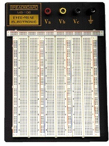
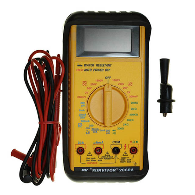
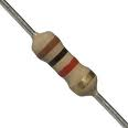
You should do this lab with a partner of your choosing. If you are having trouble finding a partner, please ask a staff member for help. You will need the following materials for today's lab. Resistors are available from the staff table at the front of the room. All other components should be available in a yellow bin at your table.
 |
 |
 |
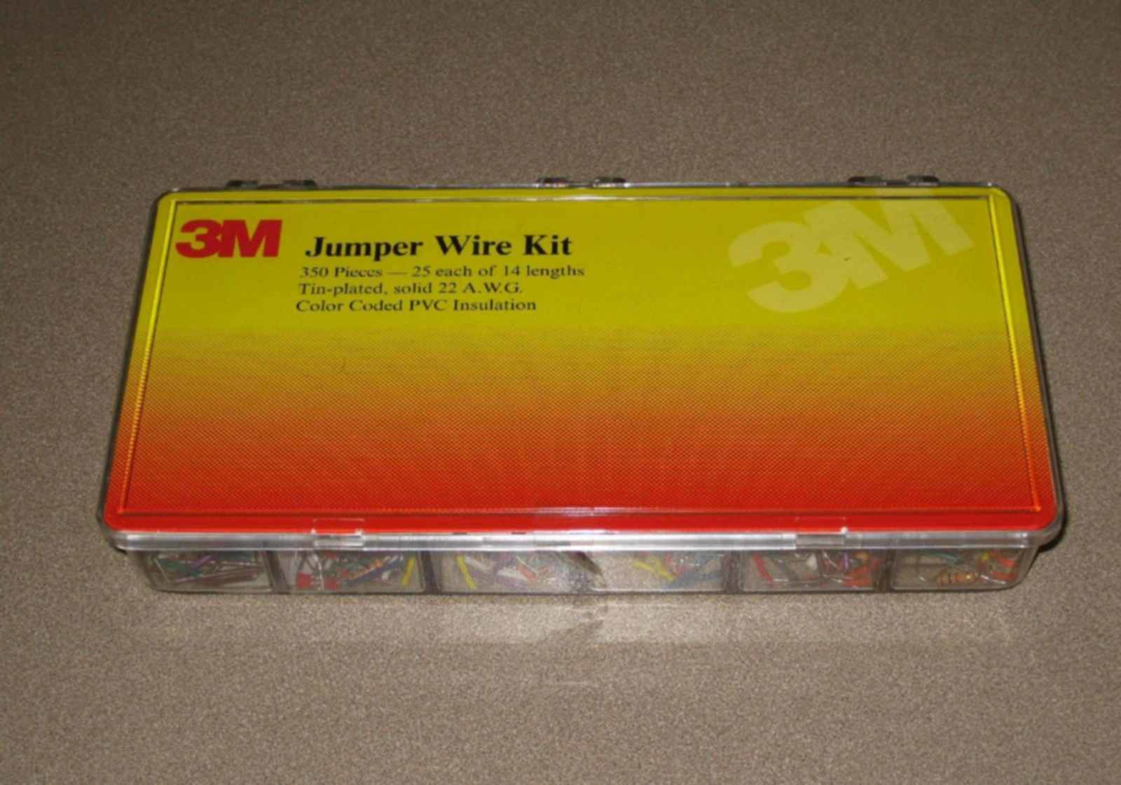 |
| Proto Board | Power Supply | Two Clip Leads | Wire Kit |
 |
 |
 |
|
| Multimeter | Resistors | Wire Cutter |
You will also need the code distribution for today's lab. You can get the code from the link above, or by running the following command on a lab laptop:
$ athrun 6.01 getFiles
2) Proto Boards
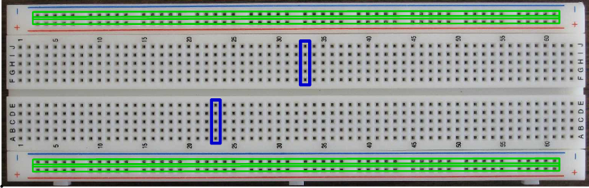
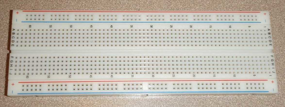
We will construct our circuits on a proto board (also known as a "breadboard"), which provides an array of holes into which wires and components can be inserted. Each hole is specified by a row letter and a column number. Certain rows and columns of the holes are electrically connected, providing a convenient way to connect components together. Specifically, each column of 5 holes in the center areas is connected internally, as indicated by two representative vertical boxes (above). If you insert one end of one component into one of the holes in a column of 5, and then insert one end of a separate component into a second hole in the same column of 5, these two components are now connected by an internal wire. Holes in the top row are connected internally, as are those in the second row, bottom row and next-to-bottom row, (indicated above by the long horizontal boxes). These rows are convenient for distributing power (we typically use +10V and ground). We will call these rows the power rail and the ground rail.
3) Circuits Maximus
We will use Circuits Maximus (a.k.a. CMax) to design, layout, and simulate
circuits before constructing them. You can start CMax by typing
cmax at the command prompt of a terminal window:
$ cmax
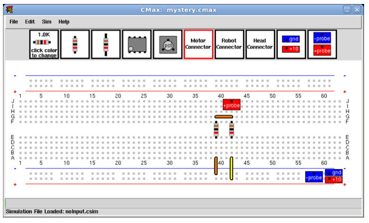
Now, select File -> Open from the menu to open the file mystery.cmax. The
figure above shows a screen-shot of the result.
In the space indicated in the handout, draw a schematic diagram for the circuit shown in the CMax window above.
Note the meter "probes", attached to the ground rail and to location J42. CMax gives you a positive and negative probe that you can put in any of the holes in the simulated protoboard. You can use them for debugging your circuit: when you run the CMax simulation, it will print out the voltage difference between the positive and negative probes.
Also, note the +10V and GND terminals, which represent our power supply as a voltage source. We will conventionally connect them to the long horizontal power rails, with blue for GND and red for +10V. However, you can move them any where you wish in CMax.

4) Build It
Construct the mystery circuit in the previous section, as follows.- Set the power supply voltage to 10V by using a meter to measure the voltage between the power supply posts marked +15V and GND (or "common", or a Ground Symbol). For information on how to use our multimeters, see: How To Use a Multimeter. Then turn off the power supply. You should always turn off the power supply when you build or modify a circuit.
- Connect 10V
and GND to the power rails of your proto board using
alligator clip leads (see figure below, where the white wire is GND and the yellow wire is +10V).
Do not unscrew the terminals on the power supply while making these
connections!
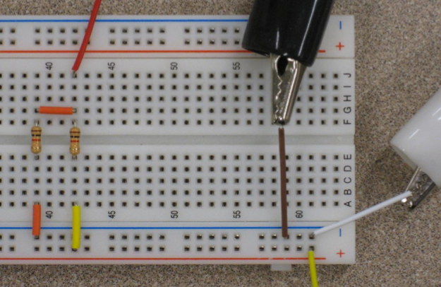
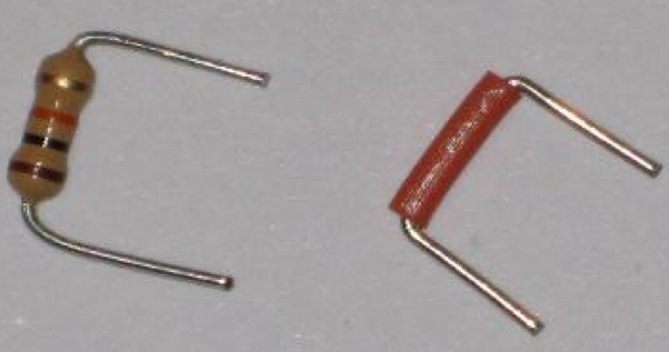
- Lay out your circuit with physical parts. Make your physical layout
look exactly like the CMax version. Note that
CMax even tells you what color wires to use! Bend the wires on
resistors and then trim their length so that the resistor has the same shape as
an orange (or yellow) wire, as illustrated in the figure below:
5) Voltage Dividers
A voltage divider is a circuit that uses resistors to generate an output voltage that is a fixed fraction of the input voltage. The following figure illustrates a voltage divider as well as the resulting relation between its input voltage $V_ i$ and output voltage $V_ o$ :
If R_1=R_2 , then \displaystyle V_ o={V_ i\over 2} .
5.1) Dividing dividers
Having in mind the ideas of modularity and abstraction, we might consider using a voltage divider to create 5V, and then using another voltage divider to cut that voltage in half again to make a voltage V_o = 2.5V. Consider the following design, where all of the resistors have 1k\Omega resistance:

5.2) Layout
Lay out this circuit using CMax (documentation for CMax is available under the "Reference Materials" tab of the course web site). Try to make your layout simple and clear. Use short wires oriented horizontally or vertically where possible. Try to avoid crossing wires, and do not run wires across other components! You will be using your layout as a guide to constructing a physical circuit. Jumbled wires are more difficult to construct correctly, and they are extremely difficult to debug!
Be sure to include probes to measure V_o.
Upload your CMax file below to verify that your circuit is implemented correctly:
Error on line 4 of question tag.
    csq_npoints = 4

ModuleNotFoundError: No module named 'simulate'
5.3) Build It
Construct your circuit with physical parts. Make your physical layout look exactly like the CMax version. Note that CMax even tells you what color wires to use! Trim the resistor leads so that the resistors lay flat against the proto board.
6) Another Divider
Now, design a voltage divider circuit with only two resistors (of any resistance value) and a 10V supply that produces voltage V_o = 2.5V? Lay out this circuit using CMax. Be sure to include probes to measure the desired voltage.
Upload your CMax file below to verify that your circuit is implemented correctly:
Error on line 4 of question tag.
    csq_npoints = 4

ModuleNotFoundError: No module named 'simulate'
6.1) Build It
Construct your circuit with physical parts. Make your physical layout look exactly like the CMax version.