How To Use A Multimeter

In 6.01, we will use digital Multimeters to measure voltages and resistances in the
circuits we build. The multimeter can be an invaluable tool for debugging
circuits, as it can be used as the equivalent of a print statement in
Python code (measuring voltages at different places in the circuit can tell you
a lot about what is going on!).
This document is intended as a "quick start" to get you up to speed with using a multimeter. For more information, the user manual for 6.01's multimeters is available at: http://www.vellemanusa.com/downloads/1/dvm850blgbnlfresdpl.pdf
Units and Maximum Values
The face of the multimeter has a display, and a switch for selecting the mode of operation. The meter can measure DC voltages between the two leads (the potential at red lead, less the potential at the black lead) when switched to one of the V options (to the left of vertical). It can also measure resistances (the resistance between the two leads) when switched to one of the \Omega options (bottom left). The options within a region specify the units of the result.
For example, the resistance options marked 2k, 20k, and 200k all display results in kilo-ohms (hence the k), but to different pecisions. The option marked 200 displays a result in ohms, and the option marked 2M displays a result in mega-ohms. Most voltage options display results in Volts, though one option displays millivolts.
Each option can only measure values up to the values marked (so the voltage option marked 2 cannot measure values greater than 2 Volts (attempting to do so will result in a "1" being displayed in the left-most column, with no other digits displayed.
Measuring Voltages
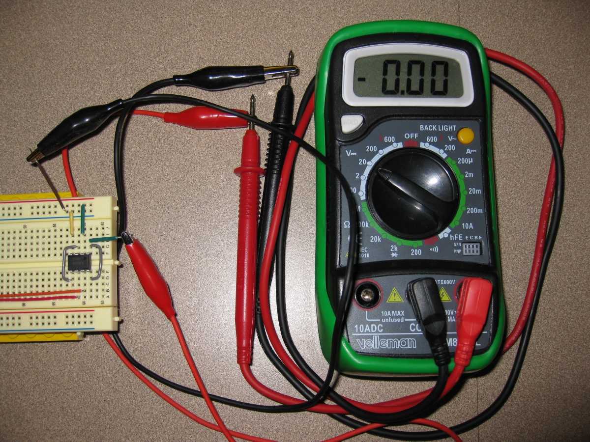
To measure a voltage between two locations on a protoboard, attach the ends of the meter's leads to short segments of wire, as shown in the picture at the top of this page. Once this is done, you can easily measure voltages by inserting the short wire segments into various places on the protoboard. If you don't do this step, it can be hard to hold the leads in place to take measurements.
To measure the voltage output of the power supply, simply place the metal end of the red lead into the power supply terminal marked +15V and the black lead into the terminal marked GND. Do not unscrew the terminals on the power supply!
Measuring Resistances
To measure the resistance of a single resistor, clip one of the multimeter's clip leads to each side of the resistor. Make sure your meter is set to one of the settings marked \Omega.
To measure the resistance between two locations on a protoboard, use short wire segments as decribed in the section above.
When measuring resistances, make sure no current is flowing through the circuit. Make sure to turn off the power supply before taking resistance measurements, as current flowing through the circuit will result in faulty measurements.
The Mark of the Beast
If you start your multimeter up and it displays 666, odds are that the "hold" button (the small grey button near the top-left of the device) was engaged when the device was switched on. Try disengaging that button, and then turning your multimeter off and on again.