Software Lab 07: Servos With a Smile
Alternate theme song here.
Files
This lab description is available as a PDF file here. There is no new code for this lab, you can use the distribution from Design Lab 6.1) Angular Position Controller
In last week's design lab, you built a circuit using a potentiometer, to control the speed (and direction!) with which a motor turned.
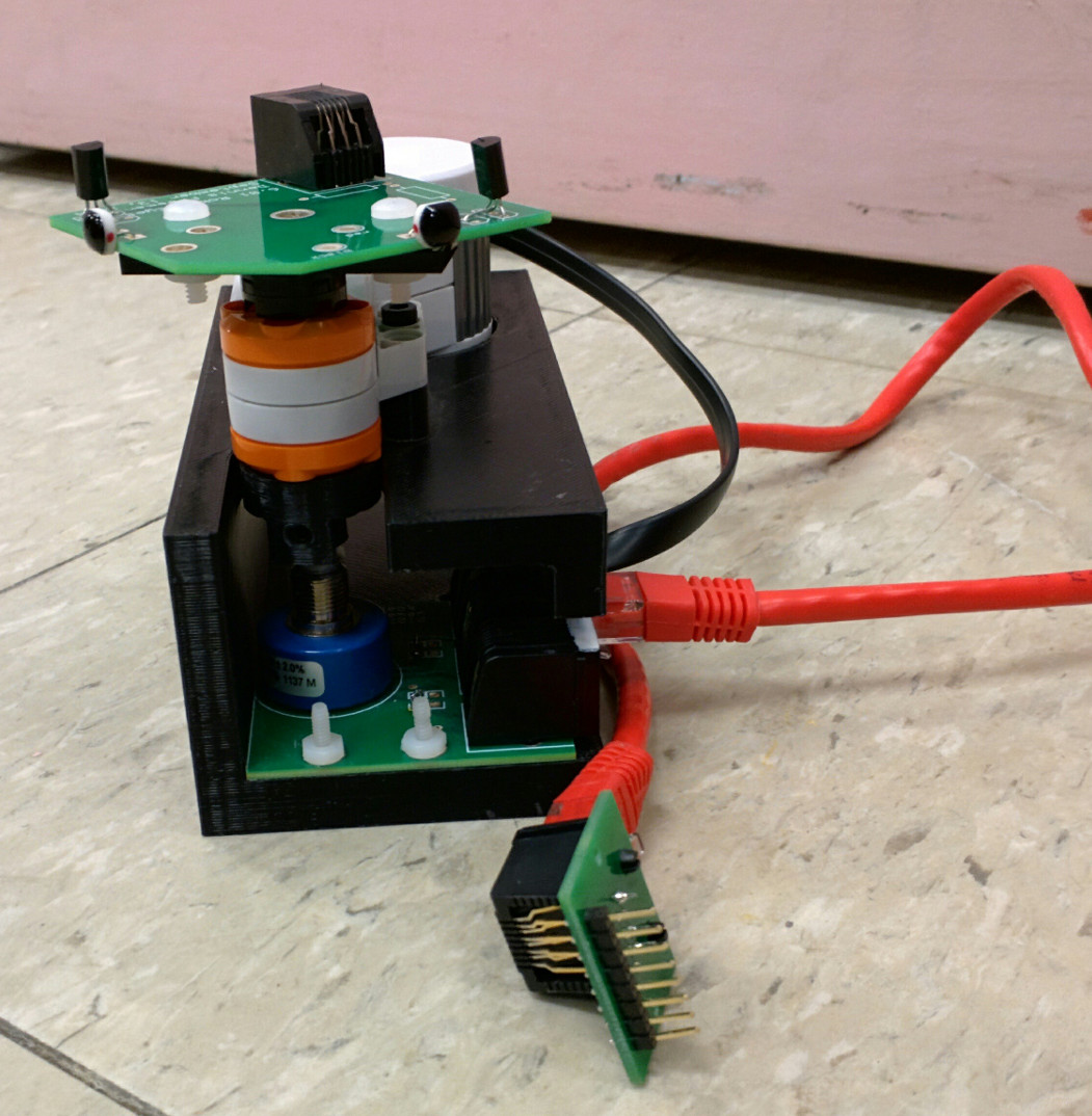
In today's lab, we will modify our circuit to control the angular position of the motor, instead of the angular velocity. For this section, we will use the robot "head," pictured below. The goal is to make a remote control of sorts, so that turning the control pot on the board causes the head to turn so that its angle matches that of the control pot.
In order to accomplish this task, we need a means of measuring the angular position of the head. This is accomplished by attaching a potentiometer to the axle of the motor to provide feedback about angle.

2) Memories, Sweet Memories
Earlier, we were able to make the motor spin in both directions by putting a voltage V_x on one side of the motor. We can create our position controller by building a similar circuit, but making this voltage proportional to the angle of the potentiometer in the head.
Under what conditions do we want the head to stop turning? What needs to be true of the voltage across the motor in order to make that happen?
How should the direction in which the head turns depend on \alpha of the input potentiometer and \alpha of the neck potentiometer?
How should the speed with which the head turns depend on \alpha of the input potentiometer and \alpha of the neck potentiometer?
Sketch a circuit for the angular position controller in your handout.
3) Layout and Simulation
Use CMax to lay out your position control circuit. Open your bidirectional speed controller using CMax and Save it into a different file (so that you can later retrieve both designs).
Delete the "Motor Connector" and substitute a "Head Connector" (not "Robot Connector"), shown below. The head connector is an 8-pin connector that connects to a motor whose shaft is connected to a potentiometer. The M+ and M- pins of the motor connect to pins 7 and 8 of the head connector, respectively.
We can access the internal potentiometer (which has 10k\Omega total resistance) via pins 1, 2, and 3. Pin 2 represents the center point. Turning the head toward the left (as would happen if V_{M+} > V_{M-}) increases the resistance between pins 3 and 2, and decreases the resistance between pins 1 and 2. Pins 4, 5, and 6 connect to photodetectors, and will be used in future labs. Do not make connections to those pins for this lab.
Test your circuit with the dl06_pot_signal_steps.csim simulation file form
last lab. Use the probe to measure the voltage on pin 2 of the neck
potentiometer.
Upload cmax code here:
Error on line 4 of question tag.
    csq_potAlphaSignal=[float(i)/100. for i in range(101)]

ModuleNotFoundError: No module named 'simulate'
4) Build It
Construct your position control circuit on your proto board. Make your physical circuit look exactly like your CMax layout. Use an 8-pin connector for the "head connector."
There are three connectors on the head: the red one, the white one, and the black one. Connect the red one to the "head connector" on your proto board using a red cable. Connect the black one to the motor using a black cable. The white one will not be used in this lab.
Test your circuit to make sure that it behaves as a position controller.
Demonstrate your working simulation and circuit. Save your plots, as well as your CMax circuit. E-mail these results to your partner.