Audio Mixer
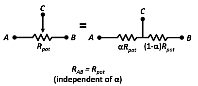
As we learned in Software Lab and Design Lab, the potentiometer can be modeled as variable voltage divider (depicted below).

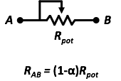
In some cases, all that is needed for a design is a variable resistor. A potentiometer can serve as a variable resistor by connecting the middle wiper arm (terminal C) to either terminal A or B as shown below. The potentiometer is now used as a two-terminal device with varying resistance*.

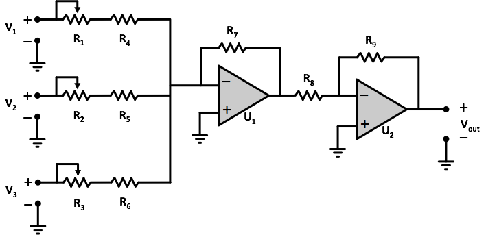
Below is the design for a simple audio mixer. An audio mixer takes in several different input signals (multiple singers, instruments, turntables, etc...), adds them together, weighted by the resistances of the corresponding variable resistor, and then amplifies the combined signal. Your personalized resistor values for this problem are listed below: Resistor Values:
- R_1 = R_2 = R_3 =1.0 k\Omega
- R_4 = R_5 = R_6 =480.0 \Omega
- R_7 =4.8 k\Omega
- R_8 =1.8 k\Omega
- R_9 =18.0 k\Omega

In our problem, each variable resistor (R_1, R_2, and R_3) has an \alpha parameter that corresponds to that input channel's weighting (\alpha_1,\alpha_2, and \alpha_3, respectively).
We will assume the input signals are the same in all cases:
- V_1 =27.0 mV
- V_2 =58.0 mV
- V_3 =91.0 mV
For the following values of the circuit's \alpha parameters, calculate the output voltage, V_{out} of the circuit to the nearest 0.01 Volts.
You can assume the power supply for both op amps is such that the op amp output has sufficient range (+ and -) to allow any calculated output.
Balanced:
\alpha_1 =0.98
\alpha_2 =0.98
\alpha_3 =0.98
Verse by MC:
\alpha_1 =0.00
\alpha_2 =1.00
\alpha_3 =0.00
Chorus/Refrain:
$\alpha_1$ =0.23\alpha_2 =0.07
\alpha_3 =0.27
*You can also just use one half of a potentiometer (from A to C or from B to C) to achieve a two-terminal variable resistor operation.