Design Lab 06: Night Ranger
Theme song for this lab can be found here.
Files
This lab description is available as a PDF file here. The code distribution is available here (zip format), or by running `athrun 6.01 getFiles` from a lab laptop or Athena computer.1) Getting Started
Do this lab with your assigned partner. You and your partner will need a laptop that reliably runs CMax.
You will also need some circuit components, which are available from the front of the room.
 |
 |
 |
 |
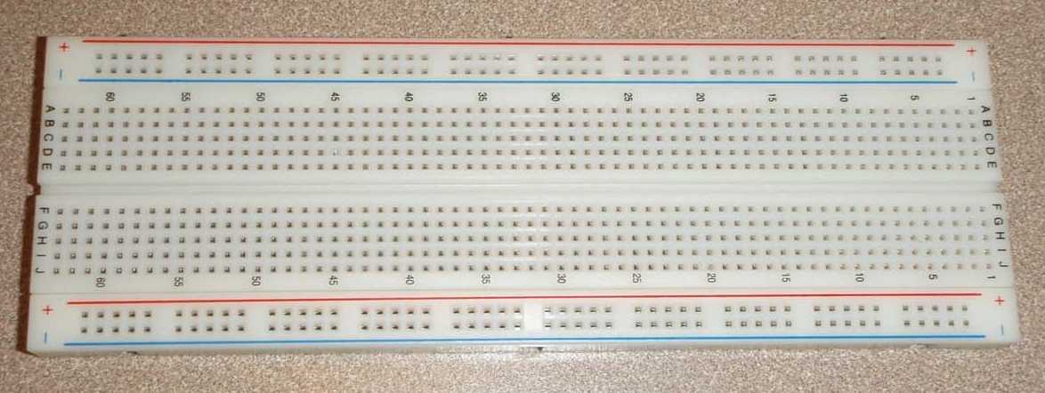
| Proto Board | Power Supply | Two Clip Leads | Wire Kit |
 |
 |
 |
 |
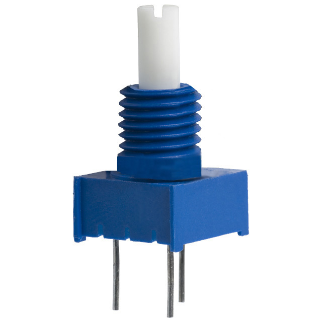
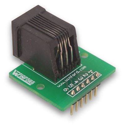
| Multimeter | Potentiometer | Six-pin Connector | Lego Motor |
 |
 |
||
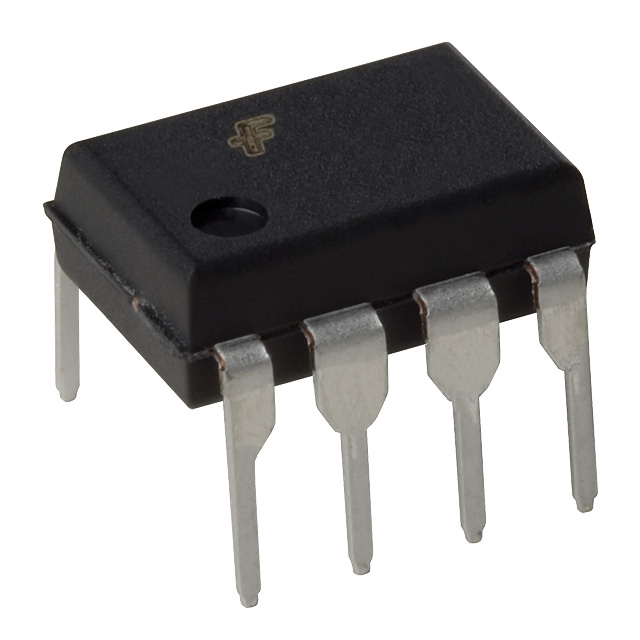
| Black Motor Cable | L272 Package (Contains 2 Op-Amps) |
2) Lego Motor
Over the next few weeks, we'll be adding a new light sensor to our robot. One key piece of this light sensor will be a motor. Ultimately, we'll use this motor to turn our sensor to face a nearby light source. For this lab, though, we'll get started by experimenting with the motor to see how it behaves and how we can control it.
2.1) Motor Resistance

The electrical port of the Lego motor attaches to a 6-pin (6 PIN!!) proto board connector via a short black cable. Notice that the two ends of the cable are different: one fits into the motor and the other fits into the 6-pin connector. The motor is driven by the voltage difference between pins 5 and 6 of the connector. We will not use pins 1-4 in this lab. Do not connect any part of your circuit to those pins.
Connect the Lego motor to a proto board using a 6-pin connector. Use a multimeter to measure the resistance r_ m of the Lego motor. Hint: You can measure resistance by setting the meter to \Omega . You should not be hooked up to the power supply when you measure resistance.
What is the resistance of the motor?
2.2) Driving the motor
The motor is designed to be driven with 0 to 10 Volts. Try it out as follows.- Adjust the voltage at the $+15$ V output of a power supply to $0 V$, and then turn the power supply off (while you connect the motor).
- Use alligator clip leads with bits of wire to connect $+15$V and **GND** to the power rails of the proto board with the 6-pin motor connector. Wire pins 5 and 6 of the motor connector to the power and ground rails, respectively.
- Use clip leads to connect a multimeter so that you can read the voltage between these pins.
- Turn on the power supply. Slowly increase the power supply voltage, and note the relation between the motor speed and applied voltage.
What is the minimum voltage required to make the motor turn?
3) Controlling motor speed
We noticed in the previous section that the motor has an angular speed that is proportional to the voltage drop across its terminals.
Our goal is to control the motor electronically. We will ultimately mount the motor on the robot and use the robot's power supply, which is constant at 10V, but we would still like to be able to have a variable voltage drop across the LEGO motor so that we can run it at different speeds. The point of this section is to find a way to use a constant-voltage power supply to get a range of motor speeds.
Return of the Potentiometer
In last week's lab, we used a potentiometer (pot) to create a variable voltage from our 10-volt supply, which we then measured using the robot's analog-to-digital converters (voltage meters). We then used this voltage to steer the robot.
Today, we would like to do roughly the same thing. In this section, we will use a potentiometer to generate a variable voltage, and we will connect that to our motor, in order to try to control the speed of the motor using a potentiometer.
Last week, we used a joystick to turn the robot; the joystick had two potentiometers in it (one that changed as you moved the joystick up and down, and one that changed as you moved the joystick left and right. Today, instead of the joystick, we will use a single, stand-alone potentiometer that comes in a small blue package:
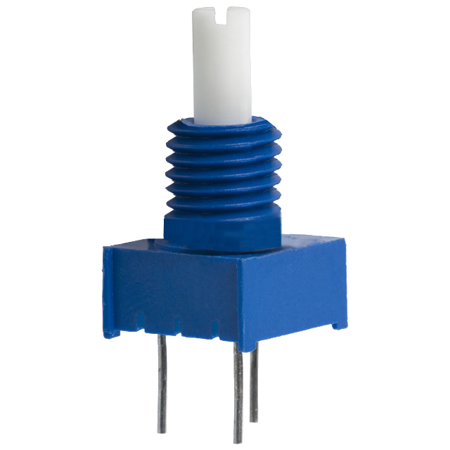
The illustrations below show how these resistors are actually connected inside the potentiometer:

As the angle varies between from \alpha=0 to \alpha=1, the resistance between the middle terminal and each of the two outside terminals will change.
Use your multimeter to measure the resistance of the pot (R_p). What is this resistance?
Now consider the following circuit, designed to generate a variable voltage across the motor, and thus a variable speed, proportional to \alpha:
3.1) Build It
Reset your power supply to 10V, and build the circuit shown in the schematic above.
3.2) Theory
Use circuit theory along with modeling the motor as a resistor to estimate, to within 0.5 volts, the voltage across the motor, for the values of \alpha given in the table below. Don't use a spreadsheet or a calculator. Use the resistance you measured earlier and what you learned in last week's labs.
Then find the value of \alpha such that the motor voltage is 5V (one-half of its maximum value), accurate to within 10^{-3}. Hint: Draw the circuit with approximate resistor values, and look for a parallel combination.
Then place these four points approximately on a graph of V_{motor} versus \alpha, and sketch a smooth curve through them.
4) Buffering the motor voltage
We can use an operational amplifier to act as a buffer that isolates the voltage divider from the motor. We use L272A operational amplifiers (op amps) that are packaged so that two op amps fit in an 8-pin DIP (Dual-Inline-Package), as shown below.

The spacing of the pins is such that the package can be conveniently inserted into a breadboard as shown above (notice that a dot marks pin 1).
A simple "buffer" circuit is shown below. We will learn how to systematically analyze op amp circuits next week. For this week, it is sufficient to understand two basic properties of op amps:
- the currents into the + and - inputs are essentially zero, and
Thus, no current will flow into the + input, and the potentiometer will operate as an unloaded voltage divider. At the same time, the voltage at the output of the op amp will equal the voltage at the + input.
- the variable voltage divider (made from the pot)
- the buffer (made from the op-amp)
- the motor
Circle each of these pieces in the schematic above.
4.1) Build It
**Reset your power supply's voltage to be $10V$.**Build the buffered divider circuit on your proto board. Measure the voltage across the motor and observe the motor's behavior as \alpha varies.
Explain to a staff member the results of your experiments, with and without buffering.
5) Bidirectional Speed Controller
This circuit allows control of the speed of the motor, but it does not allow us to change the direction the motor turns. To make our robot head turn both left and right, we will need to design a bidirectional speed controller.
The unilateral limitation of the previous circuit results from the fact that our op-amp operates from a single +10V power supply (which is the only power supply available from the robot, which will eventually have to power our "head"). A simple way to adapt our previous controller for bidirectional operation is illustrated below.
The key new component in the bidirectional speed controller is the voltage source V_X.
What value of V_X gives the most symmetric range of positive and negative speeds for the motor?
Modify the circuit diagram below to show your design. Sketch the resulting circuit diagram in your handout.
5.1) Layout and Simulation
Use CMax to lay out your bidirectional control circuit. Again, make sure to use only short horizontal or vertical wires, and avoid crossing wires.
Test your circuit with the dl06_pot_signal_steps.csim simulation file from
this week's code distribution, which simulates turning
the potentiometer first to \alpha = 0.4 and holding it there, then
turning it to \alpha = 0.5 and holding it there, and finally
turning it to \alpha = 0.6 and holding it there. Notice that this
file is also in this week's distribution (type ~ into the File name field to get back to home), rather than in the default location
for simulation files.
- turn in the negative direction when \alpha < 0.5
- stop when \alpha \approx 0.5
- turn in the position direction when \alpha > 0.5
- turn faster as |\alpha - 0.5| gets larger
Looking at the graphs from CMax, does your circuit accomplish these goals?
Paste the code for your CMax circuit below:
Error on line 4 of question tag.
    csq_potAlphaSignal=[float(i)/100. for i in range(101)]

ModuleNotFoundError: No module named 'simulate'
5.2) Build It
Build your bidirectional controller on your proto board. Make your physical circuit look exactly like your CMax layout. Test your circuit to make sure that it behaves as a bidirectional speed controller.
Demonstrate your working simulation and circuit. Explain the relation between motor speed and potentiometer angle, and how your circuit accomplishes bidirectional speed control. Save your plots, as well as your CMax circuit.
6) Fight the Power
So far, we have seen that the speed of the motor goes like the voltage drop across it. Let's do some more experiments to explore this relationship further.
Start by connecting a second motor to a separate breadboard via a 6-pin connector, with nothing else connected to it. Attach a hand-crank to the motor (ask a staff member for one).
Set your multimeter to measure voltages, and measure the voltage drop across the motor (between pins 5 and 6 of the 6-pin connector) as you turn the crank.
Motors are devices that transform electrical signals to mechanical signals. As we saw before, motors can turn voltages into speeds. But, as we have just seen, motors can also be used as generators, turning mechanical energy into electrical energy (turning speed into voltage).
6.1) Effects of Loading
Now we'll explore what happens when we add an electrical load to our circuit. In this case, we'll use a very small resistor as our load.
Start by turning the hand-crank so that the drop across the motor is approximately constant at around 4 volts.
While you are turning the crank, have your partner connect a long wire between pins 5 and 6 of the motor.
It turns out that our model of a speed-controlled voltage source was not entirely accurate, as we saw in the previous experiment. In actuality, our motor enforces a relationship between electrical and mechanical power.
Electrical power is defined as the product of voltage and current:
And for rotational systems, mechanical power is defined as the product of torque and rotational velocity:
In our system, this means that the power supplied by turning the motor should be about the same as the power required by the load.
How can you use the above to explain the effect you felt?
6.2) A Different Load
Now let's explore a slightly different load. Grab a second motor (and black cable and 6-pin connector), and connect pins 5 and 6 of the motors together. Here we'll be using one of the motors as a generator, to provide power for the other motor.
Turn the hand-crank on the motor that is providing power. What happens to the other motor?
Something very interesting is happening here. The mechanical power you provide by turning the crank is converted into electrical power by the first motor. Then the second motor turns that electrical power back into mechanical power.
In this case, we have:
How can this be explained in terms of the power in the system?
6.3) Conflict Resolution
Let's try adding a buffer between the two motors. In this case, because the voltage produced by the generator can be positive or negative, we will have to be a little bit careful about how we connect up the buffer. If you're curious as to why we do this, please ask a staff member for help.
Here is a schematic diagram for this circuit:
6.4) Crank-powered Servo Motor
Finally, connect your servo motor from checkoff 2 so that, rather than being powered from the bench supply, it is powered by your generator (but you should still be able to change the speed/direction of the motor using the potentiometer on the breadboard).
Discuss the results of your experiments with a staff member.