This document is also available as a downloadable pdf: cmax_docs.pdf

Circuits Maximus
Documentation
MIT 6.01 Introduction to EECS I
Contents
1 Getting Started
1.1 What Is CMax?
1.2 Installation
1.3 Running CMax
2 Circuit Editor
2.1 Adding Circuit Elements
2.1.1 Resistors
2.1.2 Wires
2.1.3 Power Supply
2.1.4 Voltage Probes
2.2 Modifying a Circuit
2.2.1 Moving Large Segments of a Circuit
2.3 File Management
3 Circuit Simulator
4 Keyboard Shortcuts Reference
5 Changelog
1 Getting Started
1.1 What Is CMax?
Circuits Maximus ("CMax" for short) is a simple tool that we will use in 6.01 for designing and testing circuits before constructing them from physical hardware. CMax is coded in Python and makes use of the Tkinter and matplotlib Python modules, as well as lib601.
1.2 Installation
CMax is distributed as part of 6.01's lib601 software package. Instructions for installing lib601 can be found on "Infrastructure" page of the course web site at http://mit.edu/6.01.
1.3 Running CMax
On Athena, run the following commands from a terminal:
> add -f 6.01
> CMax
On UNIX-based systems, run the following command from a terminal:
> CMax
On Windows, click the CMax shortcut in the Start Menu (it is located under "All Programs" in Windows 7).
CMax consists of two main components, the circuit editor and the circuit simulator (described in sections 2 and 3, respectively).
2 Circuit Editor
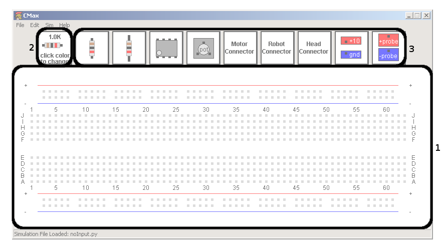
CMax's main window consists of a row of buttons and a virtual protoboard, as shown in Figure 1.
 Figure 1: A screenshot showing the 3 components of the circuit editor: the virtual protoboard (1), the prototype resistor (2), and the element toolbar (3).
2.1 Adding Circuit Elements
Circuit elements can be placed on the virtual protoboard by clicking the associated buttons in the toolbar (3). In order, the elements which can be added to the board are: short resistor, long resistor, op-amp, potentiometer, motor connector, robot connector, head connector, power supply, and voltage probe.
Clicking on an element button while holding Shift will create an instance of that element in a different orientation from what is shown. Resistors created in this manner will be rotated 90 degrees, and any other element created in this manner will be rotated 180 degrees.
Newly-created elements appear in the left-hand corner of the board, and can then be dragged to their desired location. Note that CMax allows elements to be placed in locations on the board where there are no holes; be careful not to leave any elements disconnected. CMax does not, however, allow duplicate elements to be placed on top of one another.
When a new resistor is added to the protoboard, its value is determined by the value of the prototype resistor (2). There are two ways to change the value of the prototype resistor, both of which will immediately be reflected in the prototype resistor's button:
- Clicking on one of the colored bands of the prototype resistor will change that band, cycling through all possible colors. Clicking a band while Shift is held will cycle the colors in reverse order.
- Clicking on the prototype resistor while holding Ctrl will open up a new window, into which a resistance value in ohms can be typed; acceptable inputs include "150000", "150K," and "150 kilo ohms". Resistors in CMax only allow for 2 digits of precision; more precise resistances entered into this box will be truncated to two digits. If an invalid resistance is entered, the prototype resistor will not change.
To check the value of a resistor in your circuit, (in case you forget what the colored bands mean), just place the cursor over the resistor.
Clicking on an empty spot on the protoboard and dragging to a different location will create a wire connecting those two points. Clicking and dragging one endpoint of a wire will move only that endpoint; clicking and dragging in the middle of a wire will move the entire wire.
2.1.3 Power Supply
A voltage source (either from a power supply element or from a robot connector) is required to successfully run any simulation. Clicking on the power supply button will place power and ground on the lower rails. Clicking on the power supply button with Shift held down will place power and ground on the upper rails.
2.1.4 Voltage Probes
You can use voltage probes to measure voltages on the virtual protoboard, just like using a multimeter to measure voltages in a physical circuit. Clicking on the voltage probe button will place + and - probes on the lower rails. Clicking on the voltage probe button with Shift held down will place + and - probes on the upper rails.
2.2 Modifying a Circuit
Elements can be edited once they are placed on the board in a number of ways:
- To move an element to a different location, click on the element and drag it to its desired location.
- To delete an element: either click on the element while holding Ctrl, or drag the element so that it is completely off-screen.
- Certain elements (anything but a wire, probe, or voltage source) can be rotated by clicking on the element while holding Shift.
- CMax also offers multi-level undo/redo support. The keyboard shortcut for undo is Ctrl-z, and the keyboard shortcut for redo is Ctrl-y.
2.2.1 Moving Large Segments of a Circuit
To move a large segment of a circuit, create two (invalid) wires running
north-south, extending from above the top rail to below the bottom rail. Then,
use the left and right arrow keys to slide everything in between those wires
left or right.
2.3 File Management
CMax allows for saving (Ctrl-s) and loading (Ctrl-o) of circuit
files. Please use filenames with a .cmax extension when saving and
loading circuit files.
3 Circuit Simulator
Selecting Sim → Run Simulation from the menu (keyboard
shortcut Ctrl-i) will run a simulation on your circuit, and one or more
new windows containing the simulator's output will appear. Some circuit
elements (such as potentiometers) require inputs; these inputs are specified
via a simulation file, which is a Python script that creates these inputs. You
can load a simulation file by selecting Sim → Load Sim File
from the menu (keyboard shortcut Ctrl-Shift-i); the currently-loaded
simulation file is shown in the status bar at the bottom of the window. You
will never need to write your own simulation files; we will always provide
them.
In order to get meaningful output from the simulator, your circuit must contain
some means of measuring voltages in the circuit; this usually manifests itself
as a voltage probe in the circuit. The voltage difference between any two
points can be measured by placing a + probe at one point and a - probe at the
other.
If the circuit contains an element whose input or output changes over time
(e.g. a potentiometer or motor), the simulator will also pop up one or more
windows containing graphs of these elements' behaviors over time. If the
circuit contains a potentiometer, the simulator will produce one plot of the
potentiometer's position (α) over time, and another of the probe voltage
over time. If there is a motor in your circuit, the simulator will produce a
plot of the motor's speed (in radians per second) and position (in radians)
over time.
To close all currently-open simulation windows (plots and text output), use
menu option Sim → Close Sim Windows (keyboard shortcut
Ctrl-w).
4 Keyboard Shortcuts Reference
| New File | Ctrl-n |
| Open File | Ctrl-o |
| Save File | Ctrl-s |
| Save File As | Ctrl-Shift-s |
| Reload File From Disk | Ctrl-r |
| Undo | Ctrl-z |
| Redo | Ctrl-y |
| Run Simulation | Ctrl-i |
| Load Sim File | Ctrl-Shift-i |
| Close All Simulation Windows | Ctrl-w |
| View Documentation | Ctrl-d |
| Quit | Ctrl-q |
5 Changelog
This section summarizes changes to CMax (arranged by version
number1) and tries to let
you know who to contact if something goes wrong.
version F14-6
- Update solver to model new heads (hartz)
version F13-2
- Circuit solver bugfix (hartz)
version S13-9
- Changes related to IR light sources and photodiodes (freeman)
version S13-8
- Bugfixes for dealing with Mac keybindings (larsj)
version S13-1
- Bugfixes for solving circuits containing op-amps (freeman)
version F12-4
- Several bugfixes for Windows issues, but may have broken Windows XP support (hartz)
- Fixed bug with saving plots (hartz)
version F12-3
- Updated potentiometer model (freeman)
version F12-2
- Circuit solver bugfixes (freeman)
version F12-1
- Completely new circuit solver (freeman)
- Improved LTI model of lego motor (freeman)
- New plotting package (hartz)
version 1.7
- Improved light model (bkph)
- GUI bugfixes (hartz)
- Text input for changing resistances (hartz)
version 1.6
- Simulation progress bar and resistance tooltip (hartz)
- Dragging elements off-screen now deletes them (hartz)
- Many GUI improvements (hartz)
Footnotes:
1Changes were not logged before version 1.6
File translated from
TEX
by
TTHgold,
version 4.00.
On 6 Oct 2015, 13:18.


